ICL Boulby
Saltburn-by-the-Sea
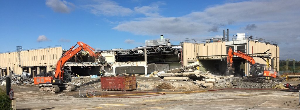
Hughes and Salvidge were appointed to the role of Principal Contractor for multi-phase demolition works at the Boulby Potash Mine in Saltburn-by-the-Sea by ICL Boulby.
Phase 1
Removal of pipework with asbestos textile outer lining within a respirator zone
All pipework was removed via the wrap and cut technique within the respirator zone – personal and background air monitoring took place during this process and any elevated fibre levels were reported to the Site Manager and Contract Manager for reassessment of the works.
- Red and white barrier tape was placed to cordon off the area with respirator signage shown.
- Operatives entered the work area wearing half face masks; cat 3 type 5/6 disposable overalls, safety shoes/boots and cut 5 gloves.
- Access to the pipework was via boom hoist. Operatives wore lanyards and harnesses clipped onto the anchor points within the boom hoists cage.
- The section of asbestos pipework was wrapped with polythene and sealed to the pipe using duct tape. Once sealed, the pipe was cut into manageable sections using a reciprocating saw and lowered to ground level using the onsite MEWP basket. Care was taken to ensure the MEWP’s SWL was not exceeded.
- Wrapped asbestos was placed into a lockable skip and once asbestos works were completed this was removed from site.
- On completion of the works, the work area was visually inspected by our appointed supervisor.
Demolition
The demolition works consisted of the removal of nine redundant areas of plant/vessels within the site, the areas were:
- Area 1 – 2A Xlr
- Area 2 – 553-020 Pumps and pits
- Area 3 – Hot leach tank pump house and equipment
- Area 4 – Hot leach tank
- Area 5 – Product leach tank
- Area 6 – Filter press hot leach tank
- Area 7 – Filtrate tank
- Area 8 – Belt filter house and tails thickener
- Area 9 – North and South fuel oil tanks and pipe bridges
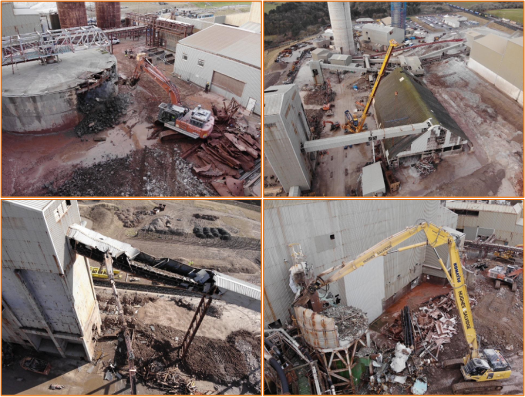
Hot Leach Tank
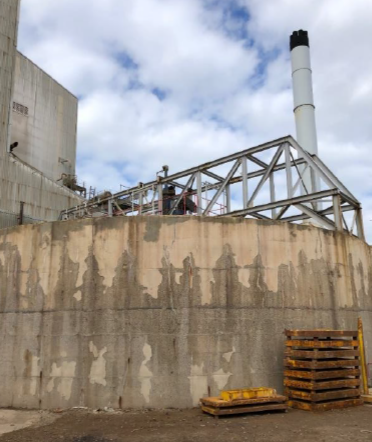
The hot leach tank was constructed of reinforced concrete with steel frameworks internally of the tank. An excavator fitted with a rotational pulveriser demolished the tank, working top down. With a section removed, internal framework was cut out mechanically to allow access to the rest of the tank structure. All materials were progressively segregated/processed ready for removal from site. A hydraulic breaker was used to remove the tank.
Product Leach Tank
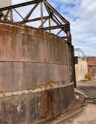
The product leach tank had a reinforced concrete base to approx. 1.5 metres with a steel frame and timber external. An excavator fitted with a rotational shear demolished the tank down to concrete level where it continued with the same methodology as on the hot leach tank.
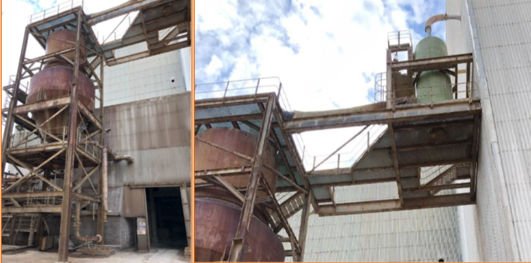
Filter Press and Filtrate Tanks
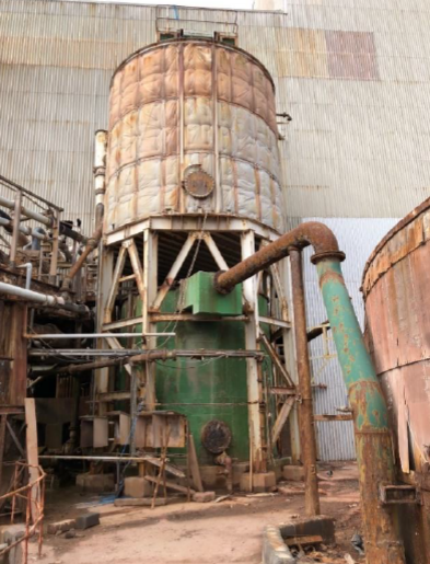
The client isolated and separate the plant prior to us commencing on site to leave an air gap between the plant and the retained features. There were live services adjacent this tank which were to be retained during the demolition. There was also a pipe which remained connected to the tank which was to be separated.
The high reach excavator removed the external insulation to the perimeter to expose the steel tank using a selector attachment. It then cut the platform located on the roof of the tank, shearing into sections and lowering to ground floor level. The tank roof and side wall were pierced using the shear attachment. The side walls were cut down in sections working around the circumference of the tank. The excavator then cut and removed the roof of the tank, lowering to ground floor level. Once the top tank had been removed, the lower tank and structural steel frame were removed.
Belt Filter Vessel and Pipebridge
The handrail and ancillary ladders/platforms were cut and lowered to ground floor level.
The tank and side walls were then pierced with the shear and progressively cut down to the base of the tank. All internal pipework was cut, lifted and lowered to ground floor level. The machine worked its way around the circumference of the tank. The second 490 excavator processed the arising materials being produced from the works. The pipebridge was removed with a combination of both machines.
The Hitachi ZX490 excavator fitted with a selector attachment held the pipebridge centrally and the high reach excavator fitted with the shear attachment cut either end. Once isolated, the pipe bridge was lowered to ground floor level where it was segregated into different waste streams and processed.
North and South fuel oil tanks and pipe bridges
The pipes once carried heavy heating oil so some product remained. During removal, an IBC was adjacent to the works area to capture any residue product. Polythene was laid on the floor to catch product leaks from the pipes during shearing.
The excavator sheared the pipe at low points to ensure vast amounts of product were not present. Once confirmed, the excavator sheared into sections and lay the pipes into the bunded area adjacent the north and fuel oil tanks. The ends were sealed with polythene and disposed of accordingly.
North and South Fuel Oil Tanks
The tanks were located within a concrete bund where other live tanks were present along with live pipework.
Prior to structural demolition commencing some items require protection using scaffolding with scaffold board protection. This was to prevent any impact from falling objects.
With scaffolding in place, the tanks were removed. The ZX490 excavator sheared the steel frame located just outside the bund. The high reach fitted with a shear attachment initially pierced the side wall followed by removal of the roof section. The side walls and roof were progressively removed working around the circumference of the tank.
Pumps And Pits and Hot Leach Tank Pump House and Equipment
The pump house was constructed of steel frame with GRP sheet external cladding and a masonry infill at low level, the annex was part of a larger structure and needed an element of enabling works to be carried out by hand method by operatives prior to mechanical demolition commencing.
Operatives working from MEWPs removed the profile cladding adjacent to the retained structure from external to expose the steel frame. The excavator then de-clad the remaining elevations and loaded the sheets into an awaiting roll-on/off container.
The asbestos removal works were then be carried out.
The steel frame was exposed so the excavator fitted with a shear attachment could start demolition on a bay-by-bay basis working top down. All plant and equipment were removed progressively during the demolition.
The bay adjacent to the retained structure had the steels hot cut by operatives using oxygen/ propane cutting equipment whilst the excavator fitted with a selector attachment held it in position to ensure no damage occurred to the retained structure.
Belt Filter House
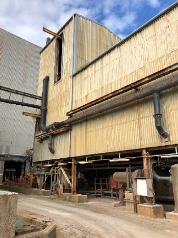
Prior to mechanical demolition works commencing there were live electrics running underneath the structure and live pumps to the north east. The high-level cable tray was protected by laying ply sheets across the top and securing in position and the lower cable tray and pumps were protected by scaffold.
The belt filter building was constructed of steel frame with external GRP cladding. Following scaffold protection, an excavator fitted with a selector attachment de-clad the structure roofs and side walls, lifting and lowering the sheets to ground floor level.
The excavator commenced by cutting the horizontal steel beams spanning between the columns a bay at a time followed by removal of the purlins and roof truss, lifting and lowering to ground floor level. The top section of the structure was removed by the high reach excavator to above the filter belt.
The excavator was then turned at an angle to remove the high-level section to the western end of the structure. The pipe bridge which ran into the adjacent structure was slung using the high reach lifting attachment whilst operatives cut either end. The pipe bridge was then lifted down to ground floor level.
The same process was adopted by de-cladding the structure followed by removal of the steel frame down the filter belt level.
With the structure at filter belt level the high reach excavator swapped over for our ZX490 excavator fitted with a shear attachment. The excavator commenced by removing sections of the filter belt, cutting into sections and lifting to ground floor level. The rubber belt was approx. 50mm thick and under tension. The excavator sheared through the belt a section at the time to release the tension. Once cut through, the machine pulled the belt and cut the belt into further sections to enable removal.
The excavator then worked through the lower structural frame cutting into manageable sections ready for loading away off site. The excavator worked through the structure before turning north east and south west.
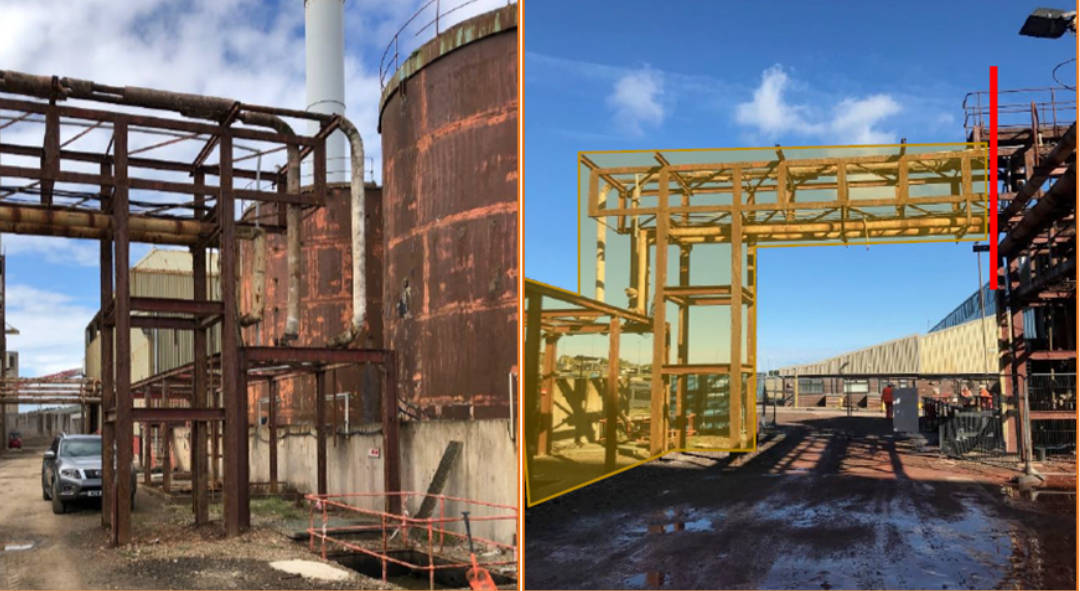
2A XLR
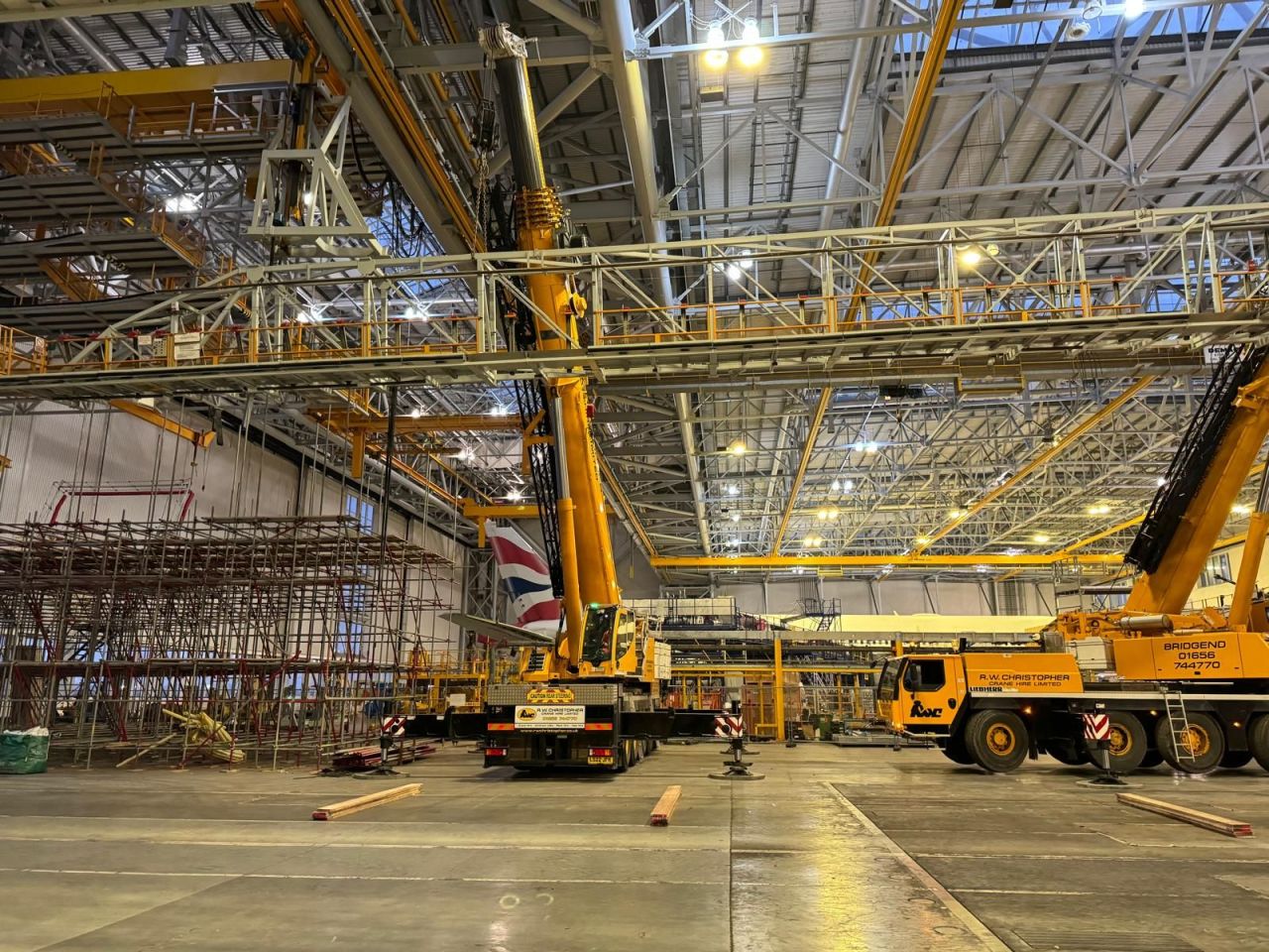
Due to the location and height of the structure, the 2A XLR was dismantled by a combination of crane and operatives dissembling the structure and plant down to approx. 10m in height.
Prior to lifts being undertaken, preparation works were undertaken by operatives using hand tools, reciprocating saws and magnetic drills. The hand tools were used to remove the external coating, magnetic drill to form a hole in the steel and then the reciprocating saw to cut and complete the opening.
Hot works were undertaken only on structural steels. Not blind cutting into vessels.
Operatives accessed the structure via boom hoist to create openings in vessels to be lifted down and to form lifting points within the steels.
All preparation works did not affect the structures stability.
Following the preparation works, a mobile crane undertook the lifts. Operatives working alongside the crane completed separation works on structural steels using oxygen/propane cutting equipment and pipework/blind cutting were undertaken by reciprocating saw.
The crane was set in position and chained to the item to be lifted prior to separation works commencing. Access was gained via a MEWP to sling and then form the separation works.
With the item slung, operatives performed the separation cuts to isolate the item enabling it to be lifted to ground level where it was processed by an excavator for later disposal.
For all hot works a hot works permit was issued.
Ancillary Pipework Removal
Access was gained to the pipework from a boom hoist. Operatives accessed the plastic pipework and cut using a reciprocating saw and lower the cut sections into the cage. The basket was then lowered to ground floor level and the pipework offloaded.
The larger diameter steel pipes were slung to the ZX490 excavator using slings whilst operatives cut sections of pipework. The sections were then lowered to ground floor level where they were further processed and loaded into roll on off containers.
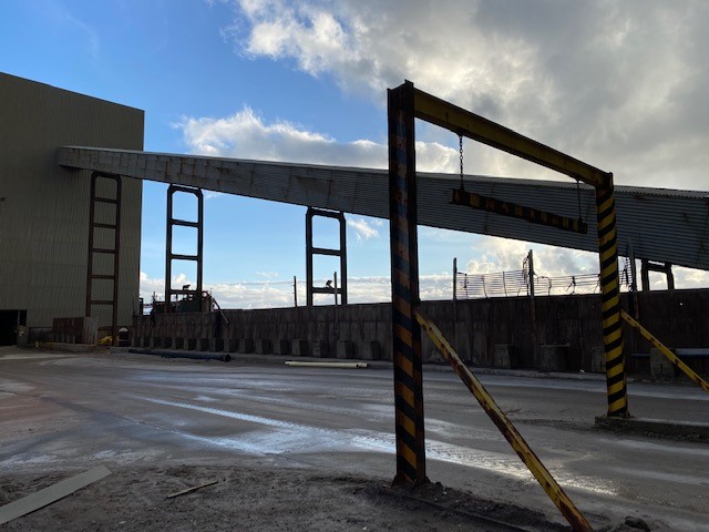
Phase 2
517-207 Conveyor
Prior to works commencing, a scaffold protection deck was installed over the Salt Feed Conveyor. The section of conveyor spanning over the salt feeder was removed by crane. Operatives working from a MEWP split the conveyor by removing the canopy and belt conveyor adjacent the stanchion support at either end of the section of conveyor to be lifted.
With the section removed above the asset to remain, the remaining sections of conveyor were removed by a high reach / standard excavator fitted with a shear attachment to cut down the structure. The conveyor was reduced in sections, firstly removing the canopy, then the conveyor and then finally removing the floor. The conveyor was removed in bays up to the supporting stanchions.
517-202 Conveyor
The steel framed shed to the western elevation of the 2000t bunker was removed prior to structural demolition of the 517-202 conveyor. Following removal, a hardcore mat was laid directly below the conveyor to provide an impact mat for falling debris.
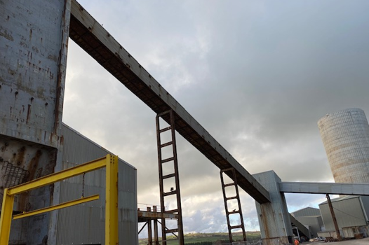
Once installed, the high reach excavator fitted with a shear attachment removed the conveyor as per the 207 conveyors. All arising materials was segregated into various waste streams
517-202C Conveyor
This section of conveyor was retained. Operatives completed enabling works to prepare the conveyor for safe removal. Where the conveyor adjoined other structures, a separation was formed. The conveyors were then slung by crane. Following removal of the conveyor, the structure to the southern elevation was made good with cladding.
Conveyor 517-204 was also retained and the same method as 517-202C were used.
517-216 Transfer Tower
Following removal of all the adjoining conveyors, the transfer tower was removed by high reach excavator.
The excavator de-clad the structure, lowering the cladding to ground floor level, and then
sheared the structure working top down, lowering to ground floor level.
Once the structure was removed down to approx. 10m a 50t excavator continued structural demolition down to floor slab level.
517-203 Conveyor
Prior to removal of the conveyor by mechanical means, each section of the conveyor adjacent to the retained structure were craned down to be processed at ground level.
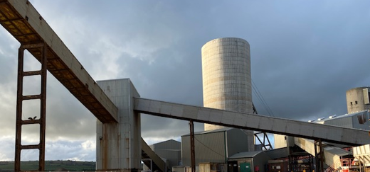
2000t Bunker 531-204
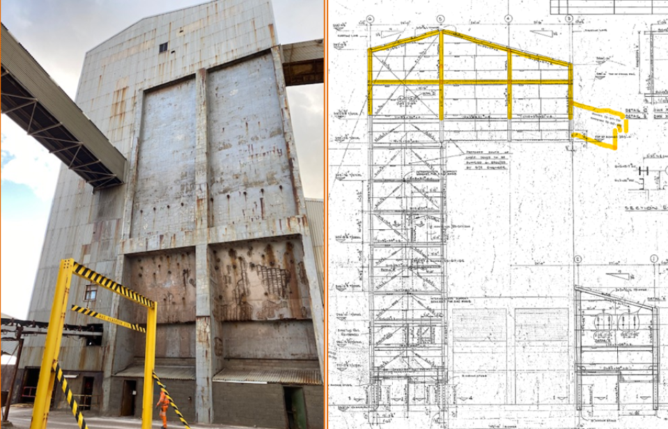
The 2000t bunker was 40.5m in height. We used our 43m high reach excavator and commenced from the western elevation working east. A hardcore mat was laid below the high reach.
The excavator de-clad the western elevation, lowering the cladding down to ground level. The excavator then de-clad the roof before cutting out the steel truss. The top of the bunker was removed working top down.
With the top section removed down of the top of the concrete bunker approx. 26m, the high reach removed the steel framed section to the northern elevation. This process continued until the steel frame was removed down approx. 15m.
The bunker was removed working top down, breaking into manageable sections. A second excavator fitted with a pulveriser attachment processed the arising materials as the structure was reduced.
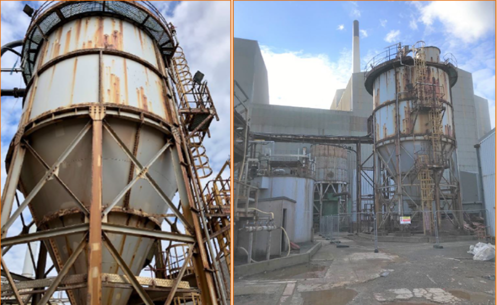
Raw Ore Silo
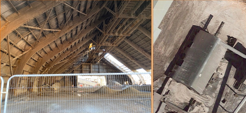
Due to the roofing being in an unstable condition the raw ore silo was removed by mechanical means with the asbestos roofing sheets in situ. In order for this to be undertaken, the internal footprint was protected to mitigate cross contamination of the soils below.
Mechanical Demolition
Periodic reassurance and personnel air monitoring was undertaken during the asbestos cement roof removal works. A respirator zone was set up around the area and all operatives working within and close to the working area wore RPE. A high reach excavator fitted with a selector attachment removed the asbestos cement as whole as possible, lifting and lowering down to ground floor level and stockpiling.
During this process the high reach was rigged up to water to supress the asbestos during the removal process. Sections of asbestos fell to the ground but these were collected on the protection mat for later disposal.
As the works progressed, the timber was segregated. With a complete bay of asbestos removed, the excavator cut the truss into manageable sections ready for loading away.
The asbestos cement on the ground was scraped from the protection mat and loaded into asbestos waste containers.
The above process was repeated throughout the building a bay at a time.
The high-level walkway / conveyor was removed a bay at a time along with the structure.
Once the structure was removed up to half way, the enabling team prepared the other half.
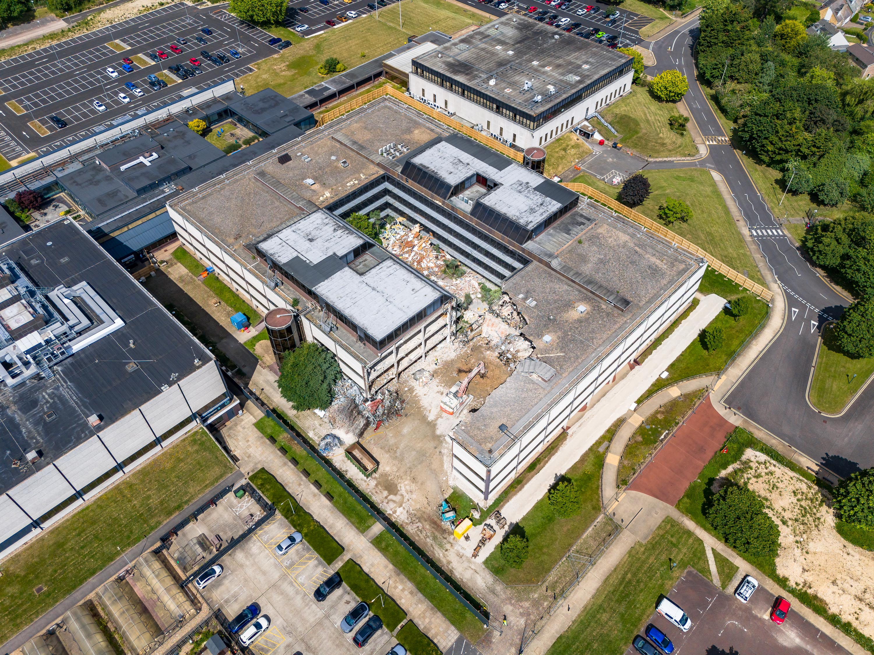
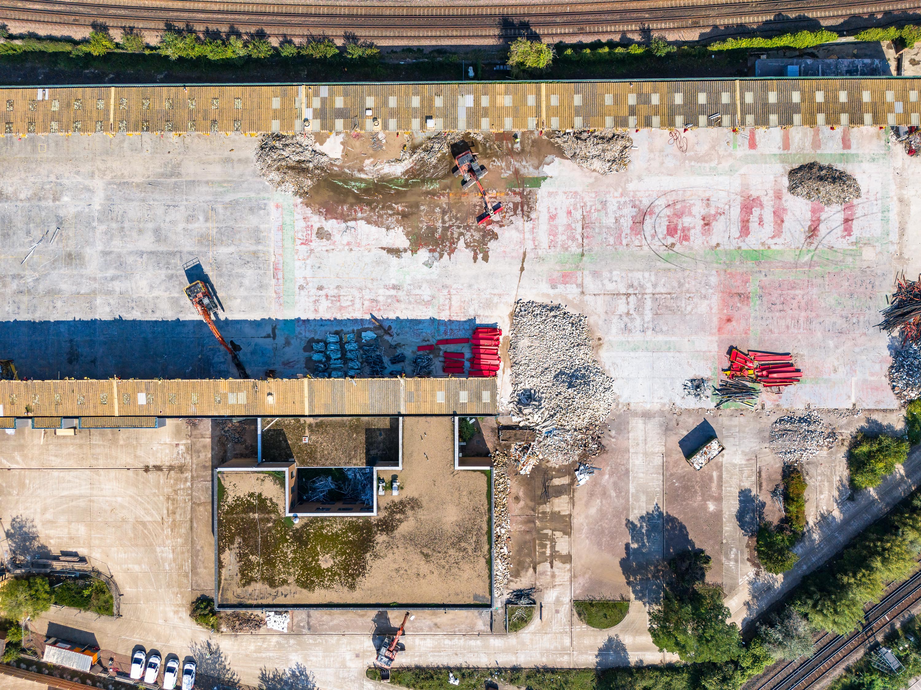
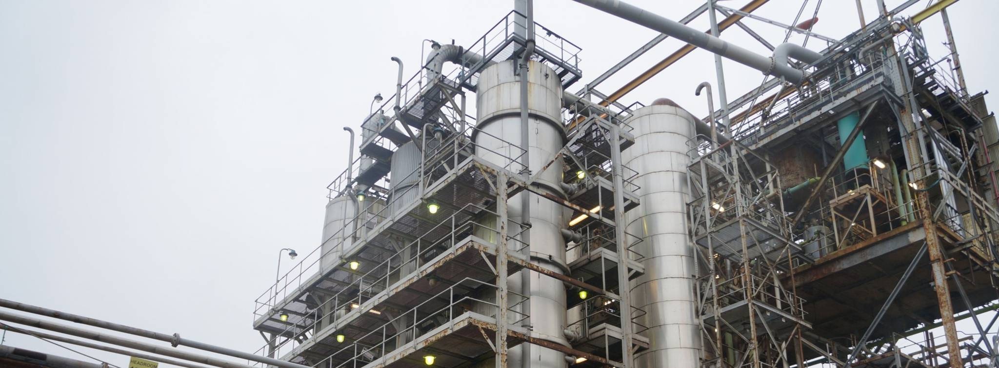
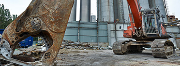
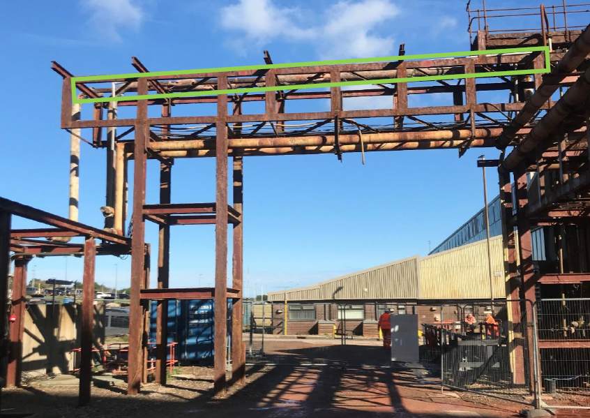
Images of the works being undertaken